...Return To Mine & Other Bonneville Car Construction Pages
.Previous Page...............B'ville Car Index Page.........................Next Page
........................................-- Chute Doors Part IV --
.................. .
.
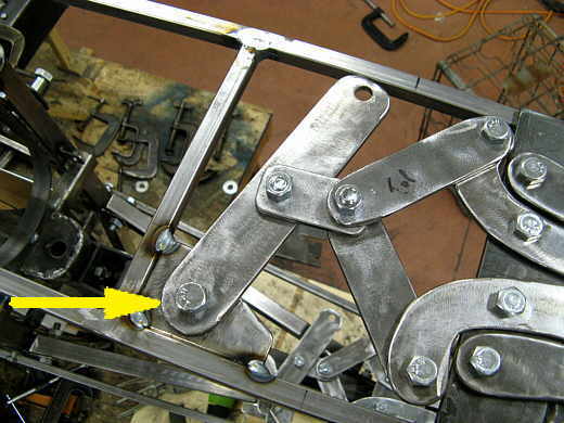
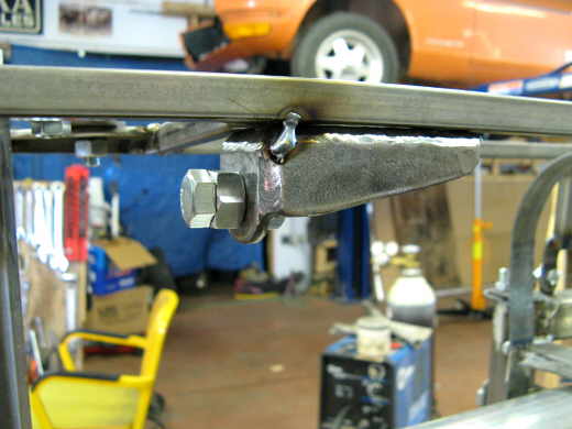
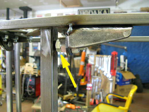
The next item was to make a pivot point (arrow) for the lever that will be pulled on (also arrow) that pulls on the hinge assembly to the right of it. A bracket was taked into the sub-frame where the arrow is. Just a reminder the sub-frame is 1/2 X 1/2 thin wall square tubing. This took care of the top hinge assemble now on to the ......................
.................. .
.
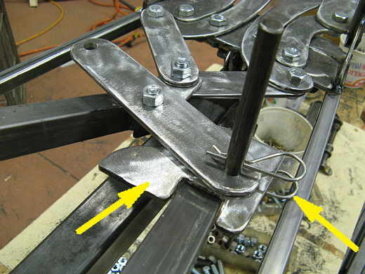
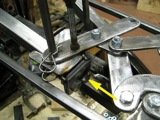
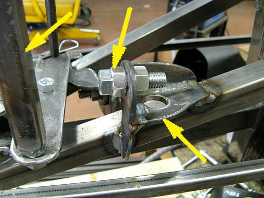
.......... bottom hinge assembly that also needed a bracket for the lever pivot point. The left arrow points to the beginning of this bracket. It is so close to a frame member that I couldn't get a bolt in the pivot point from above or below so a rod was used with a hole on the bottom of it for a hitch pin (right arrow) along with another hole above the lever arm for a second hitch pin (above the right arrow). The rod will later be cut off just above the top hitch pin. At this point the bracket is just held in position with the rod and pins.
.................. .
.
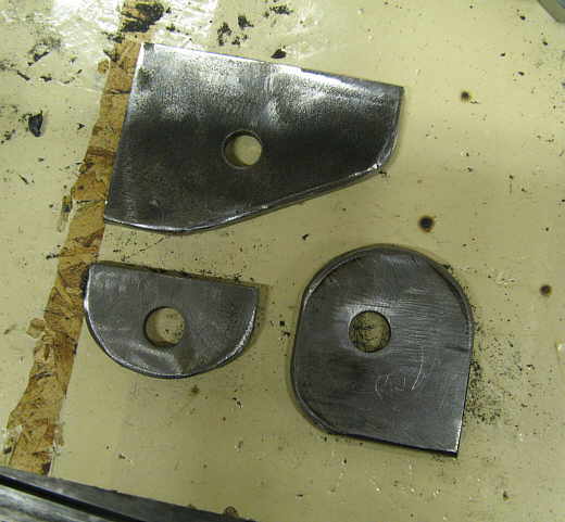
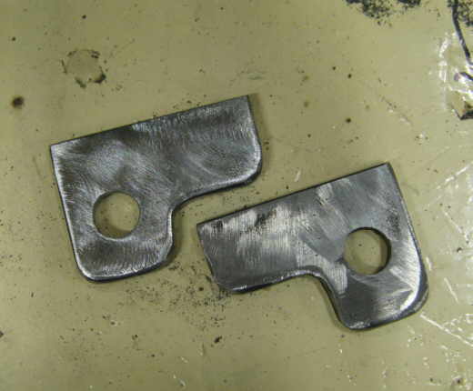
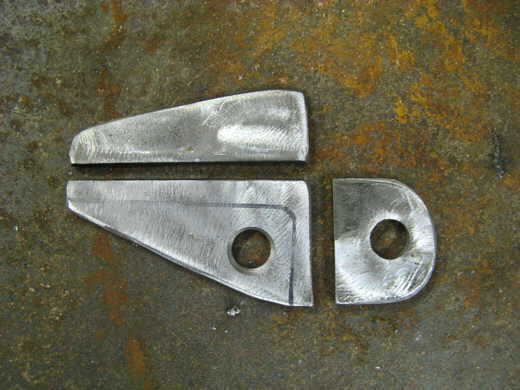
To support the bracket the two tabs at the bottom of the picture were made. The top tab never was used for this assembly.
.................. .
.
One of the new tabs was tacked to the push bar (arrow) and the other to the bracket we are trying to support and locate.
.................. .
.
Two more tabs were made to support the other side of ...................
.................. .
.
............... the bracket and tacked into place over there. One on the bracket and the other the frame member below it. At this point the lever arms are located and next is a vertical bar that will tie them together on the ends opposite from where they are pivoting. In the picture you can see a hole on the other end of the lever arm. But first here is..............
.................. .
.
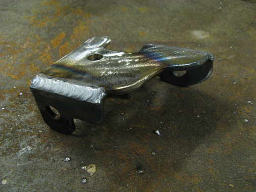
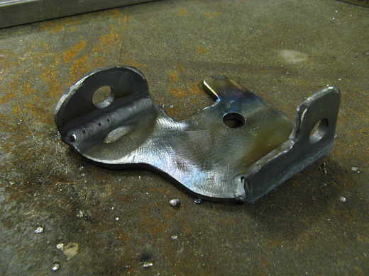
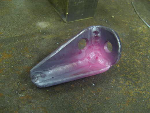
................. the bracket in the pictures above that .................................
.................. .
.
......................... had the tabs weld onto it. The holes in the tabs are the mounting holes and the other hole in the flat part is for the rod that the lever arm pivots on. Now back to the vertical rod that will pull the two lever arms at the same time.
.................. .
.
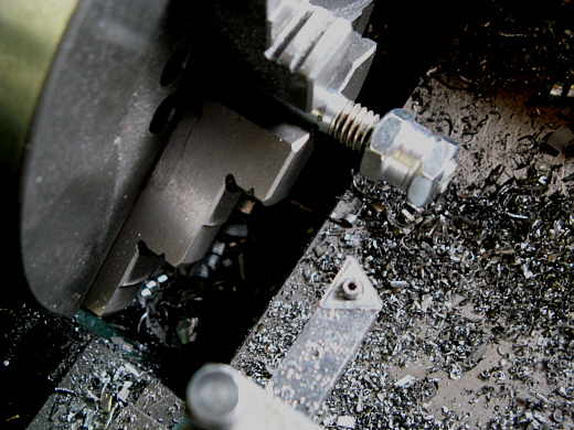
Two nuts were turned over part of their height to a diameter that would fit inside of a piece of 3/4 inch............
.................. .
.
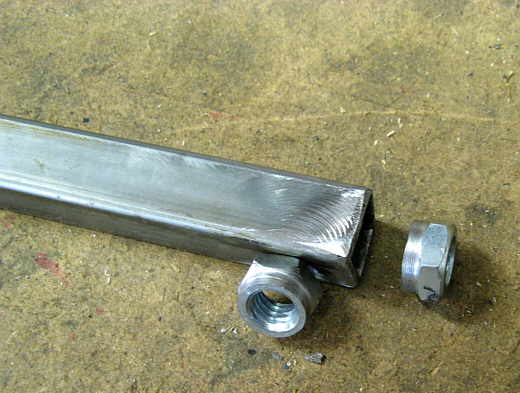
.............. square tubing that was cut to length to fit between the upper and lower lever arms. The...........
.................. .
.
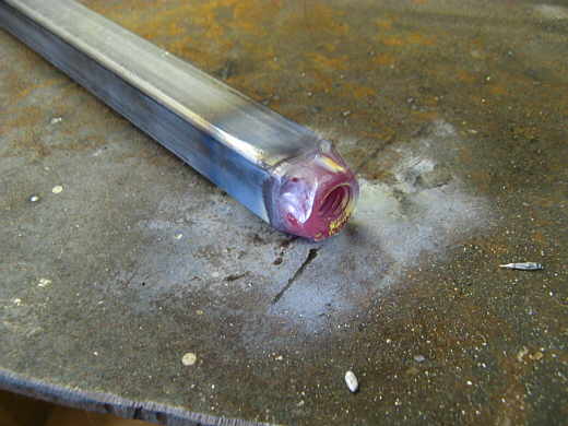
................ nuts where then tig welded into the ends of the tubing and it was finished for now and you will see it further down the age in use.
.................. .
.
Since the vertical bar was going to be pulled on with a spring I wanted stops to limit it's travel. These pieces were cut and.......
.................. .
.
...................... welded together to make the ......................
.................. .
.
.................. upper stop. The bolt can be moved in an out to limit travel.
.................. .
.
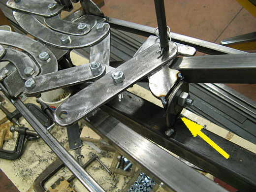
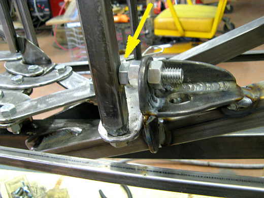
Next a lower stop was also made (right arrow) with an adjustable limiting bolt (middle arrow) that will limit the movement of the vertical bar (left arrow) that was made a few pictures back and is attached to the lever arms that accurate the hinges.
.................. .
.
This pictures shows the vertical bar against the bottom stop............
.................. .
.
..................... and this one shows it against the top stop. Next is the problem of making the bar go back and forth.
..............................................................Next Page